How the Netfilter system works
Tables, chains, rules, targets and policies
The Netfilter architecture can be intimidating to new users because of its apparently high complexity. In fact, once the component parts are understood, it is actually quite simple.
Rules
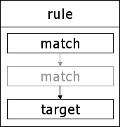
The most fundamental component of the Netfilter architecture is the rule.
At its most basic a rule consists of a series of one or more match specifications, which must all be matched for the rule to be acted upon, and a single target, which will be followed by any packet matching this rule.
The Netfilter system comes with a variety of match specifications built-in which allow packets to be matched against all manner of different criteria. These include, but are by no means limited to, the following:
- the interface which the packet arrived on
- the interface which the packet will leave on
- the protocol family of which this packet is a member
- the source address, address range, port or port range
- the destination address, address range, port or port range
- the state of the connection
Targets
Once all the match specifications of a rule have been met by a particular packet the packet will be sent to the specified target.
The Netfilter system provides us with a wealth of built-in and extension targets which can be used to perform actions on packets. These include, but are by no means limited to, the following:
- Accept the packet
- Drop the packet
- Reject the packet
- Log the packet
- Mangle the packet
The target of a rule can also be a user-defined chain. Such chains are often used to modularise parts of a firewall configuration and are analogous in some ways to subroutines in procedural languages.
Chains
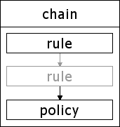
Because rules are a little small to be useful on their own the Netfilter architecture groups them in to chains.
As can be seen in the diagram Figure 2 [A Netfilter chain] a chain consists of one or more rules and a policy.
A packet entering a chain traverses the rules in order, being tested against the match specifications of each. If the match specification of that rule is met then the packet is sent to the specified target.
Some targets, such as ACCEPT and DROP, are considered to be terminal targets. When a packet is sent to such a target processing of further rules in the chain stops. Other targets, including user-defined chains, are considered to be like a subroutine. If the packet "falls through" the chain, or matches a rule with a RETURN target, then processing will be returned to the next rule in the calling chain. This is a very powerful architecture which allows for some incredibly complex configurations.
Policies
All the built-in chains provided by the Netfilter system also have a policy which will be applied to packets which pass through all the rules in the chain without encountering a terminal target.
As this will always be the last act performed by the chain it must be a terminal target such as DROP.
Tables
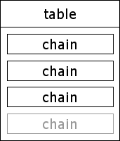
In the previous section we saw how related rules are grouped in to chains. It should come as no surprise therefore to find that related chains are further grouped in to tables.
The basic Netfilter system creates three built-in tables. These tables are used to FILTER packets, MANGLE packets, and perform NAT (Network Address Translation) on packets.
User defined chains can be created in any of these tables in addition to the built-in chains which are defined by Netfilter. Tables cannot be directly created by the administrator but they can be created by extension modules.
In the default configuration all the chains are empty and have their policy set to ACCEPT packets. In a production setup it is highly recommended that the policy of all built-in chains be set to either DROP or REJECT packets.
Built-in tables and chains
The filter table
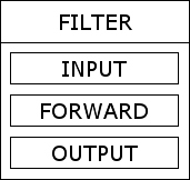
The filter table, as its name suggests, is designed to be used to filter packets. It contains three built-in chains Figure 4 [The filter table] which are described below. All packets entering, leaving, or passing through the system, will traverse at least one of the chains in this table.
The INPUT chain is used to filter packets which are being sent to the local machine. This includes packets destined for the loop-back interface but does not include packets which will be forwarded through this system.
The OUTPUT chain is used to filter packets which are being sent from the local machine. This includes packets sent from the loop-back interface but does not include packets which will be forwarded through this system.
The FORWARD chain is used to filter packets which are being forwarded through this machine. This does not include any packets which were created or will be received by the local machine.
The NAT table
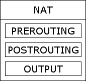
The NAT table, as you have probably guessed, is used to perform Network Address Translation on packets passing through this system. Using this table it is possible to perform SNAT (source NAT), DNAT (destination NAT) as well as MASQUERADEing which is a special, restricted form of SNAT for use with dynamic IP addresses such as those provisioned by most cable and ADSL providers. It also contains three built-in chains Figure 5 [The NAT table] which are described below.
The PREROUTING chain is used to modify packets before any routing decision is made. It is therefore mainly used for DNAT.
The POSTROUTING chain is used to modify packets after any routing decision is made. It is therefore mainly used for SNAT.
The OUTPUT chain allows for limited NAT to be performed on packets generated by the local system. Packets which are to be forwarded through this system will not traverse this chain.
The mangle table
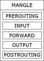
The MANGLE table is used much less often than either of the other tables. It is designed for the application of advanced effects such as QoS. Every packet which is seen by the system will pass through this table and, therefore, it contains all the chains Figure 6 [The mangle table] defined by the Netfilter architecture.
The PREROUTING chain will be traversed by any packets arriving at this system before any routing decision is made. This will, therefore, include all incoming packets regardless of their destination.
The INPUT chain will be traversed by any packets arriving at this system. Routing decisions have been made at this point so packets which are just passing through will not traverse this chain.
The FORWARD chain will be traversed by any packets which are being routed through this system.
The OUTPUT chain chain will be traversed by any packets created by this system. Routing decisions have been made at this point so packets which are just passing through will not traverse this chain.
The POSTROUTING chain will be traversed by any packets leaving this system after any routing decision is made. This will, therefore, include all outgoing packets regardless of their source.