Building a tunnelled VPN using ESP (static IPs, no NAT)
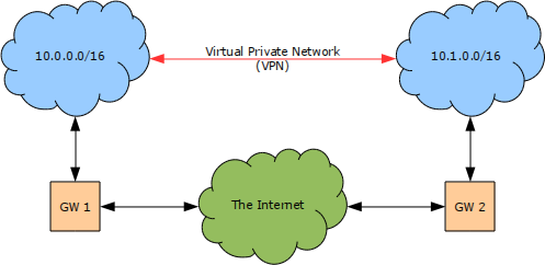
In this chapter we shall demonstrate how to create a Virtual Private Network (VPN) using the IPsec ESP protocol in tunnel mode to connect two networks together over the Internet.
As you can see in the diagram Figure 1 [Example Virtual Private Network (VPN)] the two networks in our example will use a different /16 address block each carved from the private 10.0.0.0/8 address block. Each network is connected to the Internet by a gateway machine which has a private address in the specified range and a static public IP address.
Your network will almost certainly be using a different IP range and structure and the examples below will need to be modified accordingly. If you are unfortunate enough that both networks are currently using the same IP range then one of them will have to be renumbered before they can be linked as addresses must be unique in any IP network.
Populating the Security Policy Database (SPD)
The first step is to populate the Security Policy Database (SPD) on the end-points of the VPN. The example below shows the configuration for GW-1 in the diagram Figure 1 [Example Virtual Private Network (VPN)] above.
# Flush the SPD and the SAD
spdflush;
flush;

# Security policies
spdadd 10.0.0.0/16 10.1.0.0/16 any
       -P out ipsec
       esp/tunnel/145.43.126.4-62.149.40.78/require;

spdadd 10.1.0.0/16 10.0.0.0/16 any
       -P in ipsec
       esp/tunnel/62.149.40.78-145.43.126.4/require;
The SPD on the second end-point of the VPN (GW-2 in our example) requires almost the same configuration as above however, as you can see in the example below, the in and out policy match specifiers are reversed as the tunnel is in the opposite direction when viewed from this end.
# Flush the SPD and the SAD
spdflush;
flush;

# Security policies
spdadd 10.1.0.0/16 10.0.0.0/16 any
       -P out ipsec
       esp/tunnel/62.149.40.78-145.43.126.4/require;

spdadd 10.0.0.0/16 10.1.0.0/16 any
       -P in ipsec
       esp/tunnel/145.43.126.4-62.149.40.78/require;
Routing configuration
Although we have described the IPsec tunnel when we configured the security policies we have done nothing to inform the wider operating system, specifically the routing subsystem, that the tunnel exists or that it can be used to communicate with the remote network. We can verify that this is indeed the case by displaying the existing routing table on either of the gateway hosts. In the example below we have shown the routing table for Gw-1, although the routing table for GW-2 would be similar.
Kernel IP routing table
Destination Gateway Genmask Flags Metric Ref Use Iface
145.43.126.4 0.0.0.0 255.255.255.128 U 0 0 0 wan
10.0.0.0 0.0.0.0 255.255.0.0 U 0 0 0 lan
127.0.0.0 0.0.0.0 255.0.0.0 U 0 0 0 lo
0.0.0.0 62.149.40.65 0.0.0.0 UG 0 0 0 wan
So that we can connect to our remote network without rebooting we can configure a temporary route using the command shown in the example below.
A more permanent route, which will be automatically recreated when the network interface is started, can be configured by modifying the network configuration file as shown in the example below.
config_wan=( "145.43.126.4/25" )
config_lan=( "10.0.0.0/16" )

routes_wan=( "default via 145.43.126.1" "10.1.0.0/16" )
So that the network will operate correctly in both directions a similar set of configuration procedures will be required on the other gateway host. For your convenience these procedures are detailed in the examples below.
config_wan=( "62.149.40.78/26" )
config_lan=( "10.1.0.0/16" )

routes_wan=( "default via 62.149.40.65" "10.0.0.0/16" )
Firewall configuration
In the section above we configured the routing tables to correctly attempt to send any traffic destined for the remote network over the WAN interface, presumably through our secure tunnel. There are unfortunately several minor problems with this configuration so far however. Thankfully all of these problems can be solved with a few simple additional iptables commands in your firewall configuration scripts.
The first problem is that any packets sent from either of the gateway hosts will have the wrong source address as they will be using the IP address bound to the WAN interface and not an internal address which would be sent and received over the VPN. The example iptables rule below will solve this problem by ensuring that any packets which do not have a source address on our local network, but have a destination address which is on our local network, have their source address replaced with that of the local interface appropriate for their destination. As you can see from the example it is important that this rule is added to your firewall configuration before any existing SNAT or MASQUERADE entries.
# Ensure that all packets destined for local addresses start at our local address
iptables -t nat -A POSTROUTING --src ! 10.0.0.0/8 --dst 10.0.0.0/8 -j SNAT --to-source 10.0.0.1

# Ensure that all packets destined for the Internet start at our public address
iptables -t nat -A POSTROUTING --src 10.0.0.0/8 --out-interface wan -j SNAT --to-source 62.149.40.78
The second problem with this configuration stems from the fact that the gateway hosts are also performing Network Address Translation (NAT), usually either Source NAT (SNAT) or MASQUERADING but possibly also Destination NAT (DNAT), on behalf of the local network. This will almost certainly result in the source or destination address of the packets being sent over the VPN being modified incorrectly. This issue can be resolved by adding an iptables rule to discontinue processing of any IPsec secured packets leaving over the WAN interface before any existing SNAT or MASQUERADE entries but after the rule we added in the previous example, as shown below.
# Ensure that all packets destined for local addresses start at our local address
iptables -t nat -A POSTROUTING --src ! 10.0.0.0/8 --dst 10.0.0.0/8 -j SNAT --to-source 10.0.0.1

# Ensure that any IPsec secured packets are not further mangled
iptables -t nat -A POSTROUTING --out-interface wan -m policy --dir out --pol ipsec -j ACCEPT

# Ensure that all packets destined for the Internet start at our public address
iptables -t nat -A POSTROUTING --src 10.0.0.0/8 --out-interface wan -j SNAT --to-source 62.149.40.78
The third problem is that if the IPsec configuration has not been loaded for some reason, perhaps because the racoon daemon failed to start correctly, then network traffic destined for the remote network will be sent out of the WAN interface unsecured and destined for whichever host may be listening on the appropriate address on that network segment. The iptables rules below will address this problem by instructing the kernel to REJECT any packets destined for the remote network which are not secured by IPsec both ensuring security and notifying users of a problem by sending an icmp-net-unreachable message.
# Ensure that any packets destined for a local network which are leaving over the WAN are secured with IPsec
iptables -A OUTPUT  --dst 10.0.0.0/8 --out-interface wan ! -m policy --dir out --pol ipsec -j REJECT --reject-with icmp-net-unreachable
iptables -A FORWARD --dst 10.0.0.0/8 --out-interface wan ! -m policy --dir out --pol ipsec -j REJECT --reject-with icmp-net-unreachable

# Ensure that any packets which make it this far are logged and dropped
# Clearly, these rules must come last!
iptables -A INPUT   -j LOGDROP-BLOCKED
iptables -A OUTPUT  -j LOGDROP-BLOCKED
iptables -A FORWARD -j LOGDROP-BLOCKED
Finally, we probably need to add rules to allow IPsec secured communications to traverse the firewall. An example configuration snippet containing such rules is provided below for your convenience although you will almost certainly need to modify these rules in a production environment to be considerably more specific as the example below allows all IPsec secured traffic to be sent, received and forwarded.
# Allow any packets secured by IPsec to be sent and received
iptables -A INPUT  --in-interface  wan -m policy --dir in  --pol ipsec -j ACCEPT
iptables -A OUTPUT --out-interface wan -m policy --dir out --pol ipsec -j ACCEPT

# Allow any packets secured by IPsec to be forwarded as appropriate
iptables -A FORWARD --in-interface wan --out-interface lan -m policy --dir in  --pol ipsec -j ACCEPT
iptables -A FORWARD --in-interface lan --out-interface wan -m policy --dir out --pol ipsec -j ACCEPT

# Allow any IPsec ESP protocol packets to be sent and received
iptables -A INPUT  --in-interface  wan --protocol esp -j ACCEPT
iptables -A OUTPUT --out-interface wan --protocol esp -j ACCEPT

# Allow any ISAKMP packets to be sent and received
iptables -A INPUT  --in-interface  wan --protocol udp --dport isakmp -j ACCEPT
iptables -A OUTPUT --out-interface wan --protocol udp --dport isakmp -j ACCEPT

# Ensure that any packets destined for a local network which are leaving over the WAN are secured with IPsec
iptables -A OUTPUT  --dst 10.0.0.0/8 --out-interface wan ! -m policy --dir out --pol ipsec -j REJECT --reject-with icmp-net-unreachable
iptables -A FORWARD --dst 10.0.0.0/8 --out-interface wan ! -m policy --dir out --pol ipsec -j REJECT --reject-with icmp-net-unreachable

# Ensure that any packets which make it this far are logged and dropped
# Clearly, these rules must come last!
iptables -A INPUT   -j LOGDROP-BLOCKED
iptables -A OUTPUT  -j LOGDROP-BLOCKED
iptables -A FORWARD -j LOGDROP-BLOCKED
Configuring racoon
The SPD entries, routing configuration and firewall settings above are sufficient to ensure that all traffic between the two networks will be sent over an encrypted tunnel however the tunnel cannot be created without corresponding Security Association (SA) entries being added to the Security Association Database (SAD). In this section we shall examine how to configure the racoon daemon to automatically populate the SAD whenever a new tunnel needs to be created or the encryption parameters of an existing tunnel need to be renegotiated.
Authenitcation using Pre Shared Keys (PSK)
The simplest authentication method supported by the racoon daemon uses Pre Shared Keys (PSK) which are stored in a file on each of the gateway machines. As you can see in the example below the configuration file is organised in columns with the first column containing the identity of the peer to be authenticated by the PSK with everything else on that line being considered to be the PSK itself.
vpn.hacking.co.uk 0x5e0a1bd56cb5749e8b9d1caf55f018a16aec8d24c58f7c45
It is extremely important, for obvious reasons, that this file only be readable by the root user. The command shown below can be used to ensure that this is indeed the case.
The PSK file will obviously need to be present on both of the gateway hosts as the PSK will be compared when a connection is attempted.
Security Associations (SAs) and the SAD
Now that we have configured the PSK which will be used to authenticate the peers in the VPN we can configure the racoon daemon to automatically negotiate the Security Association (SA), using the ISAKMP protocol, and add it to the Security Association Database (SAD).
path pre_shared_key "/etc/racoon/psk.txt";

listen
{
    isakmp 62.149.40.78 [500];
    isakmp_natt 62.149.40.78 [4500];
}

remote anonymous
{
    exchange_mode main;
    my_identifier fqdn "vpn.hacking.co.uk";
    nat_traversal off;
    dpd_delay 20;

    proposal
    {
        encryption_algorithm 3des;
        hash_algorithm sha1;
        authentication_method pre_shared_key;
        dh_group modp1024;
    }
}

sainfo anonymous
{
    pfs_group modp768;
    encryption_algorithm 3des;
    authentication_algorithm hmac_sha1;
    compression_algorithm deflate;
}
Once the racoon configuration file is in place the daemon can be started and added to the default run-level so that it will be started automatically.
gw-1 ~ # rc-update add racoon default
Testing the VPN
Assuming that the racoon daemon started correctly on both of the gateway hosts, and that all our other configuration options are correct, there should now be a fully functional Virtual Private Network (VPN) between the two networks using the IPsec ESP protocol in tunnel mode. You can verify that this is indeed the case using the ping utility as shown below.
PING 10.1.0.21 (10.1.0.21) 56(84) bytes of data.
64 bytes from 10.1.0.21: icmp_req=1 ttl=62 time=29.2 ms
64 bytes from 10.1.0.21: icmp_req=2 ttl=62 time=29.3 ms
64 bytes from 10.1.0.21: icmp_req=3 ttl=62 time=28.1 ms
--- 10.1.0.21 ping statistics ---
3 packets transmitted, 3 received, 0% packet loss, time 2002ms
rtt min/avg/max/mdev = 28.107/28.895/29.300/0.574 ms
The fact that you received replies to the icmp messages during the test above should be sufficient proof that the VPN is indeed working correctly however, just for completeness, the network can also be tested in the opposite direction as shown below.
PING 10.0.0.73 (10.0.0.73) 56(84) bytes of data.
64 bytes from 10.0.0.73: icmp_req=1 ttl=62 time=28.0 ms
64 bytes from 10.0.0.73: icmp_req=2 ttl=62 time=29.5 ms
64 bytes from 10.0.0.73: icmp_req=3 ttl=62 time=28.5 ms
--- 10.0.0.73 ping statistics ---
3 packets transmitted, 3 received, 0% packet loss, time 2003ms
rtt min/avg/max/mdev = 28.067/28.719/29.502/0.608 ms